WeldingWeb - Welding Community for pros and enthusiasts banner

Welding a socket wrench socket to a piece of angle iron

15K views 43 replies 17 participants last post by  vdotmatrix  
#1 ·
Before I get started on this project I wanted to make sure that my Mig Welder could successfully weld a socket to a piece of mild steel I was halfway thinking that a socket was made of some hardened steel or something exotic that a mig will not be able to weld any ideas thank you
 
#9 ·
Or that wrench that has needs bend that no one makes taking a torch and put that special bend where you needed it. Now to the OP You need to understand to that once you do weld on a socket that you change some of the strength of it so do not over torque it. Like taking a 9/16 socket and putting a 4 ft piece of steel and expect it to hold up to all that pressure that you could apply. Yes I know that is extreme example. Just to make a point,
 
#16 ·
Well that's an interesting little bit of adapting an existing tool for a different use.

For something like this even if you left the chrome plating on and welded right over it would most likely be fine for it's intended purpose.

Considering that the worse case scenario if it fails in use is that you'll startle (and possibly p!ss off) a few bees I think you'll be fine.
 
#18 ·
Considering that the worse case scenario if it fails in use is that you'll startle (and possibly p!ss off) a few bees I think you'll be fine.
Assuming you aren't deathly allergic to bee stings... :laugh:
 
#21 · (Edited)
#31 ·
Some where in all this I think he multiplies by 4 to the reading to give weight in pounds...here is what the literature says:

The weight of the hive bodies being measured is the weight registered on the torque wrench in foot- pounds divided by 0.5 because the lever arm is only half a ot long divided by 0.5 because we're only measuring the half of the hives that aren't supported on the back of the stack. That is, multiply the weight in ot-pounds on the torque wrench by 4 and you will have the weight in pounds of the stack of hives.. [the torque in foot pound per sq inch]...Once I build this thing I will calibrate it to see how accurate it is...I have 2 kinds of torque wrenches...here is a video of this thing in action: https://youtu.be/khiMIGsz3Dg
Well if this thing fails while using it and you jarr the hive box you will piss off the bees for a while.
 
#26 ·
sometimes in a tight spot I'll use a piece of flat stock... example last one I made..2" wide, 3/16 thick and about 18 inches long. took a hole saw and punched a hole to fit around the socket. put socket through hole so the square drive end was above the flat stock by about 1/8 inch....used a tig to walk around the edge...super strong. only used once but kept for future use
 
#27 ·
Oops, it wasnt a socket I welded, it was socket adapters. Black ones from harber fart. The torque wrench is also HF. The wrench is a pos and is second one. I dont wrench enuf to justify snap_on. The adapters allow me to go from 1/2" to 3/4" sockets with lever. If there is error, its from the HF pos. I need to engrave the formula on the lever.

vdotmatrix, I tig'd with ER70s and helium. I used helium because I didnt have argon.

This thread got me thinking about checking calibration of cheapo torque wrench. Can two wrenches be connected together to compare torque values? I have a brand new digital torque gauge to compare to. Just need adapter.
 

Attachments

#28 ·
whatever works works!!

a cheap Serpentine belt tool works for lots of these situations

I only weld off brands..spend way too much for my snap on stuff.
 
#30 ·
I have never tried to use 2 torque wrenches the check each other.

may not be an option for some here but all 3 of the tool trucks that stop have a torque wrench calibration tester mounted on the wall inside. they don't charge to test it.
 
#38 ·
I've made custom modified tools many times. That's what k tool and sta let were invented for. Most times you need them one time. When you need them more than once use a craftsman. I e used an s&k socket for a special tool before. No need in spending $$$$

It's simple. get a mud motor. shoot ducks in the face.
 
#40 ·
I went ahead and made another bee keeping contraption here at the this evening; this was pretty easy; I followed the example in this month's Bee Culture magazine for the same contraption.

I started with a 25 pound weight and then 55 pounds as shown. The torque reading at 55 pounds registered 33 foot-pounds. My preliminary findings are inconclusive in that the readings don't translate into real world weights...So at this point it is roughly a x2 factor.

I need to plot a graph with increasing weights to see if the device reads consistently linear.

If I knew more about the math and physics to calculate or predict the effect of shortening the angled iron or the position under the load it would save me time, trial and error producing a practical device we can use in the bee yard.

I suppose my goal is to translate ft. pound readings into kilograms or pounds so it would have more relevance to bee keepers but I guess I could record or measure relative weights in terms of torque wrench readings in ft pounds which would reflect an increase or decrease in the hive-real time.

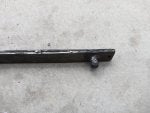
I used 2 different torque wrenches and got similar readings. I wish the calibration was more conclusive. SORRY ABOUT THE PICTURES


#41 ·
vdotmatrix, I suspected there was an error because the extended angle (2")attached to socket effects the length or leverage in my opinion. That effects your calibration.

From your numbers, I get a correction factor of 1.667. Or 60% of actual pounds.

Have you tried putting the center of socket at center of bee hive and compared to socket at end of bee hive?
 
#43 ·
I moved it all over. the left end has to be in the middle so as to pivot correctly. My friend is a physics and astronomy professor and he examined this thing and said it could only be 10-20% error. also he said I should start with the TW level and then apply force perpendicular to the plane and lift only far enough to get a ready.
 
#42 ·
The formula in this link shows how the extension changes values. The extended length of your angle past the socket is dimension E.

http://www.engineersedge.com/manufacturing_spec/torque_wrench_1.htm

Another possible way to avoid the formula is: weld a second socket at the very outside end of the angle iron and try that.

Please keep us updated. Your on to something interesting and useful. :)
 
#44 ·
Here's is friend's comment: The principle is sound and the answers you get are probably accurate within 10-20%.

The approximation you're making is that the hive is a uniform block. If you know the distribution of the masses inside that could be more accurate but I am uessing it won't make more than a few percent difference (if any).

Also depending on how the torque wrench works you may want to be careful that you start with the wrench arm perpendicular to the lifter bar at the end of the wrench. IN the same vein try to make sure the lift point is near the center of the hive box. If this is vague, see http://www.dummies.com/how-to/content/how-to-calculate-torque-that-is-not-perpendicular-.html Don't worry about the math, just look at the picture, and read the first paragraph. The lever-arm length (labelled 'r sin \theta' in picture B) that matters is the amount that is perpendicular to the force direction. You're transferring the torque both through your hand-to-wrench angle and the wench-to-lifter bracket angle. So pull perpendicular to the wrench arm and only lift the hive a little bit, and you'll be as accurate as the wrench reading can be.