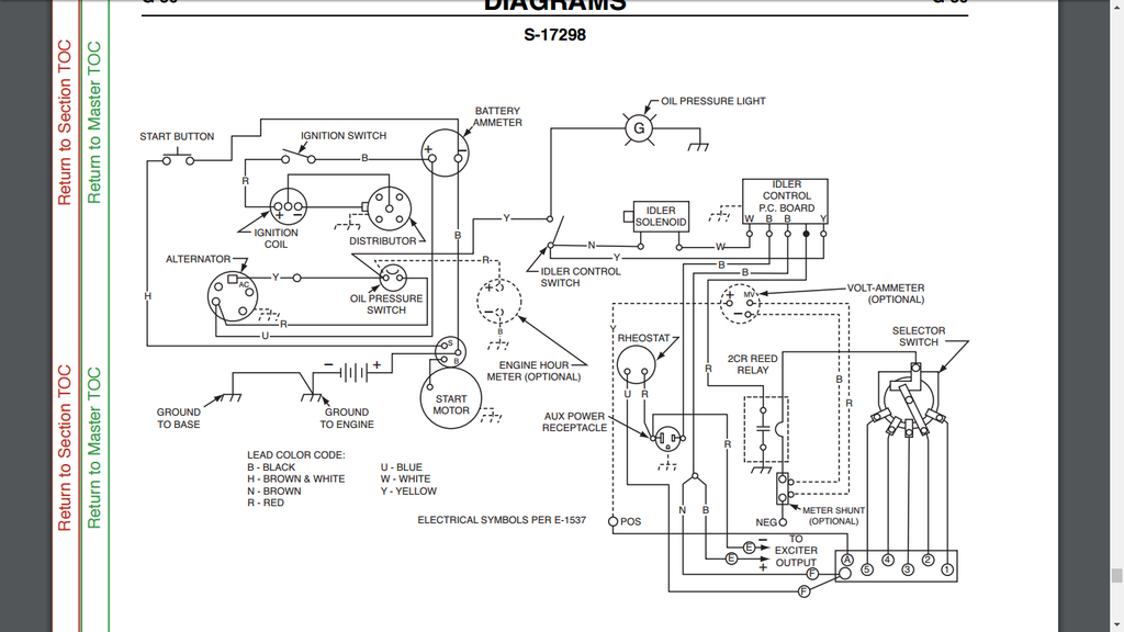
I've got the wiring diagram straight from Lincoln, but the wiring is a mess on this thing, I'll try to take pictures to show what I mean later. Could someone take a picture of their unfcked wiring at the ICB and rheostat etc for me? My rheostat wire which is supposed to be blue coming out of the generator isn't and there's two coming from the same spot but they're more black then blue when I scratch the 6 paint jobs off the wires. I'll go into further detail later. Also my idle controller stays at high idle until I start moving a wire then it'll idle down and back up quickly. Thanks in advance!

24vwelder
SA200 code 7307 wiring questions
1 reading
24vwelder
Discussion starter
69 posts
·
Joined 2017
- Add to quote Only show this user
I've got the wiring diagram straight from Lincoln, but the wiring is a mess on this thing, I'll try to take pictures to show what I mean later. Could someone take a picture of their unfcked wiring at the ICB and rheostat etc for me? My rheostat wire which is supposed to be blue coming out of the generator isn't and there's two coming from the same spot but they're more black then blue when I scratch the 6 paint jobs off the wires. I'll go into further detail later. Also my idle controller stays at high idle until I start moving a wire then it'll idle down and back up quickly. Thanks in advance!
24vwelder
Discussion starter
69 posts
·
Joined 2017
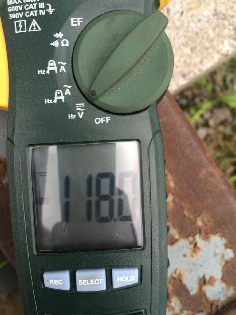
So I have 118 volts at the auxilliary, that's a good start. (Unconfirmed RPM)

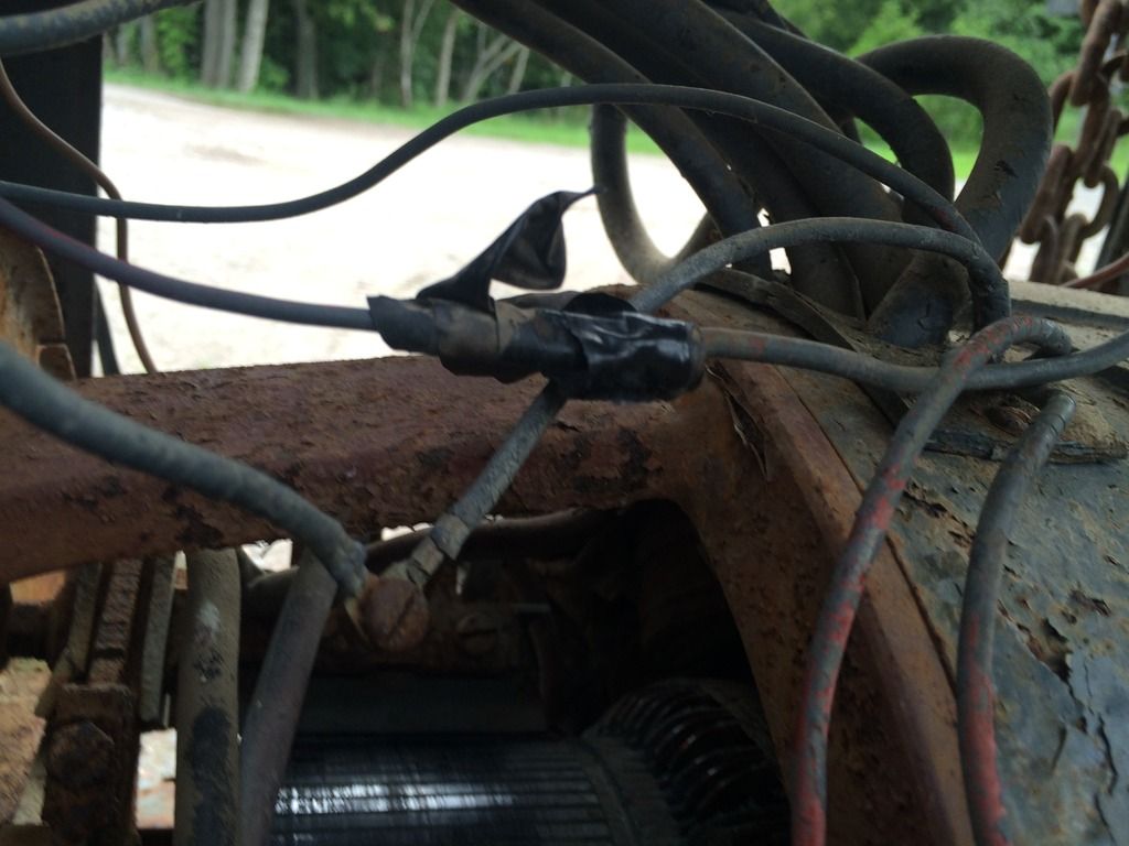
Here is where my problem is. The two that go off the bottom right of this pic go no where. They come out of the junction block as shown. They are neither blue or brown according to this diagram, so I don't know which is supposed to go to the rheostat. They're just simply black after the paint is scraped off.


I'll try to get a better look inside the gene tomorrow to see if I can get a colour on the wire as a storm rolled in right as I was trying to take pictures. Anyone with any help would be appreciated

Here is where my problem is. The two that go off the bottom right of this pic go no where. They come out of the junction block as shown. They are neither blue or brown according to this diagram, so I don't know which is supposed to go to the rheostat. They're just simply black after the paint is scraped off.


I'll try to get a better look inside the gene tomorrow to see if I can get a colour on the wire as a storm rolled in right as I was trying to take pictures. Anyone with any help would be appreciated
18,333 posts
·
Joined 2008
OK, the four small gauge wires coming out of the lead block (insulator) would be blue, brown, red and black and if you can't make out their color (if they're still factory) you'll have to trace them out to identify. They should be as follows:
Blue - comes from the 8 o'clock shunt coil (lower left as viewed from control panel) and is routed around the left side of the generator housing and then out the lead block.
Brown - comes from the 2 o'clock shunt coil (upper right) and has a short run out thru the lead block.
Red (-) - comes from the solid copper lead of the right exciter series coil and will be joined with a small machine screw under the ball of tape insulation if still factory.
Black (+) - comes directly from the right exciter brush holder stud.
The red and black are the exciter/auxiliary power that your seeing the 118VDC from.
The black exciter (+) and brown from 2 o'clock shunt coil should be connected together either in the harness after passing thru the lead block (as shown in the Lincoln wiring diagram) OR connected together at the idler board depending on year of manufacture. If connected in the harness, a single black lead will run from the joint to one "B" or "L" terminal of the idler board and then from the other "B" or "L" terminal of the idler board to the brass screw of the auxiliary power receptacle.
The red exciter (-) should connect to the silver screw of the auxiliary power receptacle and then a red lead from there to the outer terminal of the rheostat.
The blue from the 8 o'clock shunt coil should run to the center (wiper) terminal of the rheostat to complete the exciter circuit.
6,204 posts
·
Joined 2012
The wire color scheme reminds of a bag of skittles. I had bad dreams whenever I rewired my code 7307. I will try to get you a pic of the idler board in a couple hours.
Use tape and a pen to label wire colors. It should help you to troubleshoot.
Btw, your com looks like it needs to be cleaned.
Use tape and a pen to label wire colors. It should help you to troubleshoot.
Btw, your com looks like it needs to be cleaned.
18,333 posts
·
Joined 2008
Could be a corroded terminal at the white wire ("W" terminal at the far left) that provides the ground for the idler solenoid. Could also be a bad board ground thru its mounting machine screws.Also my idle controller stays at high idle until I start moving a wire then it'll idle down and back up quickly.
24vwelder
Discussion starter
69 posts
·
Joined 2017
Thanks guys! At work currently but last night I checked the brushes and had to replace all 4 with the sets from my spare welder. They were badly chipped and nearing they're end. Cleaned the comm too and exciter with scotch bright.
Will look into the tracing and labelling later today if I luck out and it doesn't rain. I think I've got it figured out from looking at the half *** job on my spare but still not sure. Thanks again guys
Will look into the tracing and labelling later today if I luck out and it doesn't rain. I think I've got it figured out from looking at the half *** job on my spare but still not sure. Thanks again guys
6,204 posts
·
Joined 2012
Heres some pics of the ICB. The white wire with red tape was supposed to be a red wire.
Attachments
-
84.7 KB Views: 385
-
92.8 KB Views: 380
-
78.8 KB Views: 380
24vwelder
Discussion starter
69 posts
·
Joined 2017
Thanks for the help guys! i think i have it figured out as of how it needs to be wired. also did a 1-wire (technically 2-wire, non self exciting) alternator setup w/o the oil switch or light (bypassed the switch for a 50 psi gauge from a Ford 9N)
Wrote up my own wiring diagram for the 1-wire with oil switch/light delete so when i re-wire it once its tore apart and back together (With ALL NEW wires!) it will be simple and i dont have to worry about going through a regular diagram and re-thinking on how i did it.
Now onto my next problem. My shunts in my running and spare welder are no good. God damn dont you love aluminum! going to be posting a new thread about preferred shunts from different brands.
138 posts
·
Joined 2017
Idle control board mounting screws can raise problems check there as in above post, panel grounds through its mounting screws, they can look o.k. and still not provide a good ground.
On your alternator if using a Delco internal regulator, non self exciting, then you will have two spade terminals numbered 1 and 2 along with the power output (BATT)
Number 2 you can jump to your BATT stud on the alternator output.
And number 1 if not wired through a alternator warning light (for resistance) then you will need to wire a diode inline with this wire going on to your ignition switch.
Problem is with wiring direct to your ignition switch with #2 when the power is turned off the alternator can back feed to the ignition and supply enough power to the coil to keep the engine running.
You can pick up isolation diodes from any alternator rebuilders and some auto part stores.
-
?
-
?
-
?
-
?
-
?
-
?
-
?
-
?
-
?
-
?
-
?
-
?
-
?
-
?
-
?
-
?
-
?
-
?
-
?
-
?
- posts
- 1.8M
- members
- 82K
- Since
- 2003
Community Forum for Welding Professionals and Enthusiasts To Interact and Learn - Free
Top Contributors this Month
View All
NotaVegetarian
328 Replies
whtbaron
226 Replies
CAVEMANN
191 Replies


