WeldingWeb - Welding Community for pros and enthusiasts banner

English Wheel build

1 reading
7.4K views 11 replies 7 participants last post by  Reebs  
#1 ·
I needed an English Wheel to use on my Egli-Vincent project.

Starting point was to machine up the lower anvil holder. The scallop in the side plates is to allow clearance on the outer race of the bearing so that there is no drag.

Anvils are from Hoosier Profiles , made of 4140.

Glen
 

Attachments

#2 · (Edited)
next up was the upper adjuster. There is quite a lot of work in building the adjuster.

I started by threading up some 1" round stock to 14tpi. It shoulders down inside the adjuster and connects onto the quill via needle thrust bearings. The quill has adjustable gibs made from 1/4" thick UHMW backed with 1/4x 1.5" wide steel plates.

The adjuster has a 6" x 6" piece of 1/2" plate welded to it and the frame has a matching piece welded to it. The two plates then get bolted together with 5/8" grade 8 bolts.
 

Attachments

#3 ·
next was to build the main frame, 3"x 5" x 1/4" wall tubing.

My little 200 amp inverter welder handled this ok, didn't have to fire up the 400 amp P+H.

It was running at about 80 % of full power on these welds and at 100%(pedal floored) on the 1/2" plate welds in the above post.

Glen
 

Attachments

#4 · (Edited)
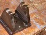
The lower tool arm was made by sawing a taper into a piece of the 3x5 tubing.

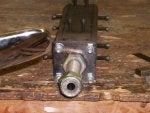
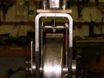
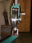
The upper yoke is from an offcut of 4x8 square tube. I milled it out to create flats for the eccentrics to run on. The eccentrics are for the quick release on the upper wheel. I made the eccentrics on the lathe and mill, fairly simple just 2 large dia pieces of round stock machined to fit holes precision bored into each side of the yoke. These pieces then get bored out for the axle, a piece of 22mm stock, or in this case a piece of 1" stainless that I turned down to 22mm. The holes for the 22mm stock were bored in 1/4" off centre, this gives a 1/2" lift on the wheel.

The yoke indexes at 90 degress as does the lower anvil holder. Just pull the locator pins and remove the two bolts, turn the assemble 90 then put the bolts in finger tight. Push the locator pins back in and then tighten the bolts.

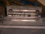
I used a little different method for indexing the lower anvil holder. It has a key milled into it's bottom side and matching keyways in a 90 degree cross milled into the plate it sits on (top side of lower tool arm)
 

Attachments

#5 ·
and here is the finished product.

I made a finger grip for the QR handle. This indexes into a pocket drilled into the yoke. The mounting bolt for the finger grip has a spring loaded ball that does the indexing. For this I just drilled out a bolt to a clearance size on a small ball from a ball bearing, pushed the spring and ball in then peened the end so that the ball could protrude about 1/3 out but not fall out.

The Ewheel sits on pads (rubber at front) when in use. When it is time to move it, the front pivoting castor gets lower by way of the 1" acme thread. When the front pad picks up three or four inches, the rear pads are then clear of the floor as the protruding rear non- pivoting castors are now taking the weight. It's pretty easy to roll it around then.

Glen
 

Attachments

#7 ·
Worntorn, Excellent quality as usual. You are definately up to your usual high quality standard. What is the need for the english wheel? Are you remaking the tank or fenders? Either way, love the pics.
Bob
 
#8 · (Edited)
thanks Bob & Cory

I checked around some but couldn't find anyone to make the Al. fenders for the Egli project. Also, I was tempted to try building the tank and seat cowl in al.

An English wheel was a must!

I've started in by pounding out the fenders, you can see them in the Egli thread. Seat is next, then the tank, but I will need to build a wooden buck for that.

Glen